
One of the concerns that I have been raising within the Council Chambers (and numerous meetings and emails) has to do with stability of the dam reservoir walls. This has been a particularly pertinent issue for me since the Ratepayer has assumed the role of last-man-standing in relation to cost overruns.
To clear up the current situation about overruns the situation is that the irrigator contribution to the dam as has been advertised for some time included a $15 million dollar cash input raised through water subscriptions and a loan from the Government agency CIIL to the tune of $25 million. This total of $40 million irrigator input has since been refined. That figure includes the total amount of irrigator contribution to dam construction including any cost overrun ($1.5 million share of the first $3million overruns), and other non-capital contributions (full details in the soon to be released in the consultation document). So if you are using the previously advertised figures, then the ratepayer will be responsible for ALL other overruns.
Given that albatross around the neck of the ratepayer I have been trying to find out just what is included in our P95 (the 95% guarantee that we can build the dam on or under budget). Because I am no engineer, and I am assuming that the construction of the dam has been well reviewed, I have to accept that the figures given to construct the dam will be accurate. The greatest potential for cost overruns as I see them are contained in the reservoir (no pun intended).
Why is the reservoir an issue?
It may not be an issue, but I have been unable to get that reassurance from the information I have been presented with to date.

What this map shows (and I apologise for the quality) with the various yellow and green shapes are the slips and slumps in the reservoir immediate boundaries. What it does not show are the slips and collapsing mountain (mount Rintoll) in the headwaters of the reservoir.
My initial concern was around the amount of sedimentation infill we can expect in the dam. This is not to be confused with a water turbidity issue, but in terms of alluvial rock and gravel infill.
When the head of Engineering came back with his findings of what engineering reports stated that the expected rate of sedimentation build up is 1000m3 (or 1000 Tons – I have had two versions) per annum and he added that that will not be an issue. In fact, he went on to add that it wouldn’t matter if their figure was out by a factor of ten times.
On that point I agree, it wouldn’t matter if their figure was out by a factor of ten in terms of impact on water storage in the reservoir. However, the fact that they could be wrong about the volume of sedimentation build up does not then become a matter of throwing zero’s at the initial result. Why 10 why not 100 or 100,000 times an incorrect figure.
If we are going to go down that road do we also say what if the price is out by ten times, instead of $82 million does it matter if it is $820 million? Or what if we say that the longevity of the dam is out by ten times, instead of a 100 year water supply solution we have a 10 year water supply solution for $82 million dollars? Or again, instead of water security for a 1 in 60 year drought it is a water security of supply for a 1 in 6 year drought event. Does a factor of ten times matter in the greater scheme of things?
Does a factor of ten times matter in the greater scheme of things?

I believe that if the engineer reports are not correct then we should be questioning more than just the sedimentation build up, we should be questioning their ability to ascertain the watertightness of the reservoir walls. If we start to fill the reservoir after building an $82 million dollar dam and find that the hills are leaking water so that the dam does not fill do we walk away? Or do we spend another $100 million to remediate the reservoir (ratepayer being the sole contributor)?
I could be barking up the wrong tree – as council staff would assure me. However, upon reading the Tonkin and Taylor reports that I was directed to read, I came away without the assuredness that the staff have there is not an issue here. I have included some excerpts below (emphasis mine) of these reports for those hardy enough to want to read more, or for those entirely without a life who would like to read the reports in full follow this link.
First a quick summary. Because the ratepayer is soley responsible ($1.5m excluded) of dam overrun costs this dam needs to come in on budget. Currently there is a 5% chance that this project could bankrupt the Tasman district. And by bankrupt I compare the Cromwell dam “In the end, the investigation and stabilisation work cost a staggering $936 million. Work on the Nine-Mile landslide alone, reportedly cost $60 million.” (source ). When things go wrong there is no limit to potential costs.
In the same blog refernced above there is a discussion on the Roxburgh dam – now choked with sedimentation. The Tonkin and Taylor reports highlight the number and size of existing slips along the sides of the reservoir. The figure of 1000m3 of sedimentation per annum do not reflect the volumes of gravel anecdotally moving down the river now, without the added impact of a large body of water in the valley waterlogging the toe of these 80,000m3 slips, plus the added effect of wave action. Not to mention the effects of extreme weather events or earthquakes which may not affect the dam structure but could potentially cause Kaikora scale landslides.
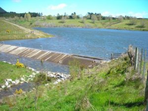
Wave action is one of the problems that was identified early on with the Kainui / Wai-iti Dam. As you can see this dam in entirely different country to the proposed Waimea Dam.
Another point raised by the author of the Clutha blog was in relation to decommissioning costs of the Roxburgh dam. They said that if decommissioning costs were taken into account most large dams would not be constructed. I tried to have to the cost share ratified in the Waimea dam term sheet, but I was laughed out of the council chamber. Consequently, there is no mention of who will pay for the decommissioning of the Waimea dam in the event that it becomes necessary (a little present from our generation to those who will follow trying to sort that out in court).
This information is presented purely to add to an informed debate as we enter the consultation phase for the Waimea Dam.
Following Exceprts taken from:
Lee Valley Dam Feasibility Investigations Geotechnical Investigation Report T&T Ref. 24727.204
WAIMEA WATER AUGMENTATION COMMITTEE December 2009
Geological investigations (T&T 2012) for the dam identified a number of potential slope instability or landslide features around the potential reservoir. (p7)
5.2.2 Reservoir Induced Instability
It is anticipated that the inundation of the valley to form the reservoir will raise groundwater levels by up to 45 m around the perimeter of the impoundment and this will have a local destabilising effect on slopes. During operation, reservoir levels are likely to fluctuate by up to 25 m over several weeks. The slopes that will be most affected are those that are blanketed by thick soil deposits and those where local instability is already evident. Solifluction deposits, particularly those upstream of the dam on the left bank are likely to experience surface erosion and shallow instability within the zone of drawdown and extending upslope of the maximum operating level. This may disrupt the forestry access road into Flat Creek. Elsewhere soil deposits will be locally eroded by wave action within the normal operating zone but it is unlikely that landslips will extend significantly above top water level. (p.26)
6.4 Landslide generated waves
Geological investigations (T&T 2012) for the dam identified a number of potential slope instability or landslide features around the potential reservoir. These are shown on the Reservoir Landslide Map presented in the Design Drawings. Waves generated by a landslide into or within the reservoir may have the potential to overtop the dam crest and cause damage.(p42)
Two landslides were selected for detailed hydrodynamic modelling as follows:
• Scenario 1, landslide (labelled as landslide 6 and 7 on drawing 27425-GEO-09) at
approximately ch 1400 m upstream of the dam, being the worst case likely landslide
to occur under OBFL conditions (triggered by extreme rainfall) with an approximate volume of 84,000 m3
• Scenario 2, landslide (labelled as landslide 3 on drawing 27425-GEO-09) at
approximately ch 600-800 m upstream of the dam, being the worst likely landslide to
occur under OBE and NTWL conditions (triggered by seismic event) with an
approximate volume of 80,000 m3. (p.42)
Significant quantities of felled timber have been abandoned on steep slopes in the
catchment. The possibility that the timber could mobilise during a construction flood event and need to be passed down the downstream face of the dam without damaging the mesh has been considered. Logs could potentially be mobilised by the following mechanisms:
a Logs being inundated in the area immediately upstream by water ponded behind the downstream stage. This would be low velocity water but may cause logs to float
downstream
b Logs being floated by high velocity in the river due to an extreme inflow, substantially larger than recent river flows
c Local landslips into the storage in areas where the logs are stacked.
Standing trees and felled logs that will be inundated by the final reservoir are expected to be removed for water quality purposes as part of the reservoir clearing works, and this should negate the potential for the mechanism listed as “a” above. The mechanism listed as “c” above is also expected to be negated through a process involving inspection of slopes immediately surrounding the storage for potential zones of instability and removal of any logs that could be affected by the unstable zones identified. (p.81)
Cawthron (2009) recommended that for water quality reasons the reservoir, dam site, borrow areas, spoil disposal areas and contractor site compound are clear felled of trees and vegetation and that debris is removed from the same areas. We endorse forest and debris removal as a priority, as there is otherwise the risk that the dam could be damaged by debris during construction and river diversion.
An exception to forest clearance is where there are trees that currently cover possible landslides. The geotechnical investigations (Appendix F) conclude that removing trees above reservoir level on landslides may reduce the stability of the landslides. Therefore the trees above reservoir level on the landslides identified in Appendix F should remain insitu. (p.148)
The following exceprts are taken from:
Lee Valley Dam Feasibility Investigations Geotechnical Investigation Report T&T Ref. 24727.204
WAIMEA WATER AUGMENTATION COMMITTEE December 2009
No active large landslides have been identified in the potential reservoir footprint.
However, solifluction deposits, that blanket the lower level reservoir slopes, are
subject to shallow slumping and erosion. It is anticipated that groundwater levels
will be raised by the reservoir inundation, and local instability associated with
solifluction slopes can be expected.(p.5)
3.2 Faulting and Seismicity
A number of large historical earthquakes would have been felt at the potential dam site.
The magnitude and level of ground shaking at the dam site associated with recorded
events are documented in www.geonet.org.nz are as follows:
Table 1 – Historical earthquakes
Earthquake Date Magnitude Felt Intensity
Marlborough 1848 M7.8 MMVII
Murchison 1929 M7.8 MM VII-MMIII
Inangahua 1968 M7.1 MMV-MMVI
Peak ground accelerations for these events would have been in the range <0.15g for
MMV, 0.15g-0.25g for MMVII and 0.25g-0.45g for MMVIII.
The GNS New Zealand Active Faults database
http://maps.gns.cri.nz/website/af/viewer.htm indicates that seismic hazard at the site is
dominated by the Alpine Fault (Wairau Segment) located 21 km to the south-east of the
site and the Waimea Fault located 8.5 km to the north-west of the dam site.
Research by GNS 2003 [Ref. 4] indicates that the latest estimate of the recurrence interval
for displacement on the Wairau Fault is 1,600 years. A major earthquake associated with
this fault could result in both lateral and vertical offsets and severe ground shaking in the
vicinity of the fault. The associated earthquake is estimated to be an M7.6 event.
Based on the coincidence of the elapsed time and recurrence interval, and the coincidence
of accumulated strain and single event displacement history, GNS have concluded that
there is a relatively high risk of such an event.
Many segments of the faults in the Waimea–Flaxmore fault system are active, with the
ground on the south-eastern side of the major faults being uplifted. The major faults in
the system are, from northwest to southeast, Flaxmore, Waimea, Eighty-eight and
Whangamoa. The Whangamoa Fault is approximately 3.5 km west of the potential dam
site but in this region it is not classed as an active fault. Active traces are associated with
the Waimea Fault that is located at the western end of the Wairoa Gorge (8.5 km from the
dam site).
The seismic hazard presented by the Waimea Fault has been assessed by Fraser et al, 2006
[Ref. 5]. They carried out trenching of Quaternary terrace surfaces at the mouth of the
Wairoa Gorge that have been displaced by the Waimea Fault. Three fault displacements
have been determined within the last 18,000 years with an average recurrence interval of
6,000 years. A magnitude M7.0 earthquake has been estimated for rupture of the Waimea
Fault.
There are several other faults mapped within the Richmond Ranges. The following faults
have been reviewed as part of this study as being in regional proximity to the proposed
dam, but are not considered to be active, (M Johnston pers comm).
· Lucy Creek Fault: It forms the boundary between the Caples Terrane rocks and Patuki
Melange. The contact is generally poorly exposed and varies from between 35 and
200m wide. It is offset by other faults.
· Anslow Fault: The Anslow Fault is best exposed in Anslow Creek adjacent to a culvert
on the main forestry access road to the dam site. At this locality there is a zone of
crushed Rai Formation rocks about 30 m wide. It is inferred to splay into two or more
segments north-east of the Lee Valley. The fault is assessed (M Johnston Pers Com) as
a relatively minor one and there is no evidence that it is active.
· Faults adjacent to the Croiselles Melange: Several north-east trending lineations are
associated with the Croiselles Melange and it appears that several landslides have
originated where serpentinitic rocks are sheared out along faults.
· Wards Pass and Totara Saddle Faults: The Wards Pass Fault is a relatively major fault
with a well developed crushed zone and has been traced from the Alpine Fault
northwards into the Wairoa catchment where it crosses the Lee River 3.5 km upstream
of the potential dam site. North of the dam site the fault has not been identified.
Approximately 3 km north of the proposed dam site is the Totara Saddle Fault, which
trends ENE and appears to be the most south-western part of the Queen Charlotte
Fault Zone. Neither the Wards Pass nor the Totara Saddle Fault displays evidence
indicating that it is active.
· Intraformational Faults within the Rai Formation: Several crushed and sheared zones,
trending both north-east and north-west, are recognised within the Rai Formation in
the vicinity of the project area. They are aligned parallel to the major tectonic faults
and also are common at lithological contacts. (p.15-17)
3.3.3 Reservoir Slope Features
Main Valley
Upstream of the dam site the valley is aligned in a northerly direction. The valley floor
widens upstream of Ch12,650 m through to Ch13,400 m where Waterfall Creek enters the
valley. A gently inclined alluvial fan at the mouth of Waterfall Creek overlies a broad flat
terrace in the main valley.
The right bank slopes upstream of Waterfall Creek to Ch14,000 m are characterised by
actively eroding bluffs (>45° ) rising to between 40 and 50 m above the river bed. Upslope
of the bluffs between Ch13,500 m and Ch14,000 m a landslide deposit, partly overtopped
by solifluction deposits, extends onto a terrace remnant approximately 40 m above the
river. Higher slopes are inclined at 20° to 26° and are extensively blanketed by
solifluction deposits.
On the left bank, between the dam site and Ch13,500 m the ridge rises to RL500 m. An
extensive apron of solifluction deposits lying at 20 to 35° blankets the lower slopes up to
about RL260 m. Bedrock slopes above this are inclined at 34 to 40°. A gully with gentle
gradient falling to the north, just below and parallel to the ridge crest, forms a prominent
lineament that is also evident crossing ridge lines to the south.
Slopes further upstream, and on the northern side of the Flat Creek arm are generally
steep (38 to 42°) and contain rock bluffs. In contrast, the southern slopes of Flat Creek are
more gently inclined (30-34°) and are characterised by few outcrops.
Upstream of Ch14,500 m the river is entrenched in a narrow gorge with steep bluffs rising
to about 100 m above river level on both sides of the valley. These bluffs have not been
inspected, but from aerial photographs examined, they appear to be stable.
Large landslides have formed in a variety of rock types in the head of creeks draining into
the Lee River upstream of the reservoir, but are beyond the likely reservoir extent and
have not been inspected.
Waterfall Creek Arm
Waterfall Creek enters the main valley on the true right side. Within the extent of the
reservoir it is V shaped in profile. The side slopes above the reservoir level are inclined at
38 to 42 ° on the northern side and 31 to 41° on the southern side. The slopes are planar in
profile but are incised by narrow steep sided gullies spaced at 100 to 200 m. Gullies on
the northern side are actively eroding. Flatter topography, inferred to be a landslide (LS2)
infills a tributary gully above the upstream end of the reservoir on the southern side of
Waterfall Creek. Upstream and east of the reservoir, Waterfall Creek is significantly
asymmetric in profile (northern slopes 38 to 41° and southern slopes 12 to 29°), and the
southern side of the valley is inferred to be a large bedrock landslide that is buttressed
against the northern slope.
3.4 Reservoir and Dam Site Geology
3.4.1 Rai Formation
The Rai Formation is the foundation bedrock at the proposed dam site and is the
predominant bedrock exposed in the reservoir. It consists of Palaeozoic age, moderately
strong to strong jointed greywacke (well indurated fine sandstone) and argillite (well
indurated siltstone and mudstone) that is commonly fissile. There is only limited
exposure of mudstone sequences.
Bedded sequences dominate the Rai Formation and although individual beds vary
considerably in thickness they are typically spaced at 100 mm. Bedding throughout the
area dips predominantly to the north-west and meso folding within the sequence is
common, particularly within the argillaceous rocks. Individual bedding layers are not
continuous over large distances. They appear to have been sheared prior to
metamorphism. This original bedding plane shear has been healed by quartz
recrystallisation during metamorphism (annealed). However, a preferred weakness exists
along bedding and subsequent phases of tectonic deformation and local deformation of
slopes by creep and/or seismic shaking has led to localised reshearing along bedding.
3.4.2 Star Formation
The Star Formation, dominated by indurated massive to poorly bedded greywacke, has
been mapped within the proposed reservoir near Ch14,500 m and forms much of the
upper left bank slopes of the reservoir. It also provides the main armour rock within the
active river bed.
3.4.3 Patuki Melange
The Patuki Melange outcrops in the Lee River downstream of the dam site and forms the
higher slopes to the west of the study area. It consists of blocks of indurated gabbro
dolerite and basalt rock, ranging from less than 1 m to over 1 km in size, in a serpentinitic
matrix. Investigations carried out during Stage 2 revealed a high variability in rock
quality and weathering over short distances.
3.4.4 Croiselles Melange
The Croiselles Melange is mapped locally on the ridges above the right bank upslope of
the reservoir and in the upper catchment of Waterfall Creek. It consists of blocks of
ultramafic and mafic rocks and siltstone, enclosed within a serpentinite or sedimentary
matrix. It is commonly characterised by widespread instability.
3.4.5 Alluvial Gravels
Alluvial gravels form a thin veneer over rock in the bed of the Lee River, underlie low (2-4
m above the river) terraces beside the river and are mapped in isolated terrace remnants
on the valley sides at heights of up to 60 m above the river. They are described as follows.
Low Level Terrace Gravel
Low level terrace deposits on the right bank are preserved between Ch11,700 m and
12,000 m, 12,300 m and 12,420 m, 12,540 m and 12,600 m and in a wide fan deposit at the
confluence of the Lee River and Waterfall Creek between Ch12,800 m and 13,350 m.
Low level terraces are preserved on the left bank between Ch12,100 m and 12,300 m.
The deposits consist of sandy GRAVEL, with less than 20% finer than coarse silt size.
They include rounded boulders dominated by very strong hard green, grey and purplishred
greywacke, rarely more than 0.8 m across. Clasts of weaker, finer-grained lithologies,
such as argillite, are less abundant and are considerably smaller in size. Gravel clasts are
typically unweathered and unconsolidated. The deposits vary in thickness from one to
three metres.
Mid Level and High Level Terrace Gravel
Mid Level terrace deposits up to 6 m thick occur locally on a poorly preserved rock bench
about 15 to 20 m above river bed level, and are preserved at RL170 m on the left bank at
the dam site. Isolated high level deposits, some at 40 m above the river bed and
occasional deposits at 60 m above the river bed, are preserved within the valley. At the
dam site a gravel deposit is locally preserved on the left bank in the Lee Valley Road at
RL210-215 m.
The deposits consist of silty GRAVEL. Gravel clasts are moderately to highly weathered
sandstone, well rounded and yellow or brown in colour. The fines fraction varies from
sand to silt, with some clay. These deposits are generally capped by 1 to 6 m of slope
deposits.(p.18-20)
3.4.6 Slope Deposits
Solifluction Deposits
Solifluction deposits are the product of periglacial physical erosion of bedrock through
repeated freeze-thaw cycles.
Solifluction deposits are extensively distributed on the slopes in the Lee Valley. They
locally form mappable units in excess of 10 m thick where they infill fossil gullies and
form apron deposits below steep bedrock slopes. Large deposits of solifluction are
mapped on the left abutment of the dam site and on the left bank upstream of the dam
between Ch12,700 m and 12,800 m and 13,000 m to 13,200 m. No large deposits have been
mapped on the right bank near the dam site. Solifluction deposits are not observed below
the level of the mid level terraces (i.e. in the lowest 10-20° of slope).
Solifluction deposits are stratified soil deposits, layered parallel to the slope. They are
dominatedby gravelly SAND and sandy (fine) GRAVEL with some silt and traces of clay.
Fines, when present, classify as low plasticity silt (ML). These soils are very stiff to dense.
They are yellow brown in colour and the coarse fraction clasts are moderately weathered.
Poorly graded fine to medium GRAVEL layers are occasionally present. These layers are
highly porous and contain some redeposited clay that binds the gravel clasts. The poorly
graded gravel layers are loose.
Groundwater seepage is often observed within the solifluction deposits near or at the
interface with the underlying bedrock.
Colluvium and Scree
Colluvium and scree deposits are formed by on-going slope erosion. In contrast to the
solifluction deposits that are mainly preserved within gullies or as discrete mappable
bodies, colluvium deposits are widespread and generally form a thin veneer less than
2 m thick over bedrock on slopes up to about 40°. Scree deposits are common downslope
of rock bluffs, and outcrops and in narrow gullies on steep slopes (greater than 35°and up
to 50°). They are of limited lateral extent.
Colluvium deposits are gravelly SANDS and gravelly SILTS; gravel clasts are typically
slightly weathered and include angular bedrock (scree) clasts and rounded alluvial clasts.
Scree deposits are mainly medium GRAVEL, unweathered to slightly weathered. (p.20)
Landslide Deposits
Landslide deposits, derived from bedrock or soil slide or flow are not widespread within
the immediate vicinity of the dam site, or within the margins of the reservoir but do occur
within the broader Lee River catchment.
A large bedrock landslide deposit in Rai Formation greywacke is evident on the left bank,
500 m downstream of the proposed dam site, between Ch11,700 and 11,900 m. This
landslide has developed on a steep slope (45-50°) where bedrock defects are unfavourably
oriented, and where the toe of the slope is actively eroded by a river meander.
An ancient and eroded earthflow deposit that contains debris derived from Croiselles
Melange has been mapped on the right bank at Ch13,600 m and 14,000 m overlying a rock
bench and high level alluvium at RL210 m. A large landslide deposit incorporating
Croiselles Melange and Rai Formation is also inferred upstream of the reservoir extent in
Waterfall Creek.
Rockfall deposits are locally evident at the foot of bluffs, mainly Ch13,300 m and
13,800 m on the right bank.
Landslide deposits derived from recent slippage involving solifluction, colluvium and
scree are common within steep gullies and on slopes cut to form forestry roads
but are rare on the vast majority of slopes.(p.21)
5.2.1 Existing Stability
The preliminary review of the existing stability of slopes upstream of the potential dam
site has identified no active large landslides that would extend into the reservoir area.
Small areas of active erosion are noted in the heads of many gullies, and locally, small
volume rockfall is evident downslope of rock bluffs. Existing landslides in the Waterfall
Creek catchment are remote from the reservoir and the one large landslide deposit
mapped on the right bank upstream of Waterfall Creek is largely eroded and now
blanketed by younger slope deposits.
A large landslide in Rai Formation greywacke downstream of the dam site has developed
where bedrock defects are unfavourably oriented (notably bedding strikes parallel to the
slope) and where river erosion has formed a high (150 m) slope that is inclined at 45°-50°.
No similar slope features are evident within the reservoir and, in general, slopes
underlain by Rai Formation greywacke lie at between 35 and 42°.
Solifluction deposits that are well exposed in road batters upstream of the dam blanket
the lower portion of slopes. There is historical evidence of local shallow landslips when
the slopes have been deforested, but no evidence of deep seated instability. These
deposits (which are probably in excess of 10,000 years old) are not overlain by rockfall or
bedrock landslide debris. (p.32)
5.2.2 Reservoir Induced Instability
It is anticipated that the inundation of the valley to form the reservoir will raise
groundwater levels by up to 45 m around the perimeter of the impoundment and this will
have a local destabilising effect on slopes. During operation, reservoir levels are likely to
fluctuate by up to 25 m over several weeks.
The slopes that will be most affected are those that are blanketed by thick soil deposits
and those where local instability is already evident. Solifluction deposits, particularly
those upstream of the dam on the left bank are likely to experience surface erosion and
shallow instability within the zone of drawdown and extending upslope of the maximum
operating level. This may disrupt the forestry access road into Flat Creek. Elsewhere soil
deposits will be locally eroded by wave action within the normal operating zone but it is
unlikely that landslips will extend significantly above top water level.
5.2.3 Earthquake Induced Landslides
The valley slopes will, from time to time, experience ground shaking associated with
seismic events that is of a similar magnitude to that experienced in the past. The absence
of landslide debris overlying solifluction or terrace deposits in the area to be inundated
suggests that these slopes have not failed due to large scale instability during earthquakes
during the last 10,000 years. However, as a result of the presence of the reservoir,
groundwater levels will be higher than in the recent geological past and this may increase
the risk of slope failure during shaking.Preliminary stability modelling of the western,
left slope between Ch13,000 m and 13,500 m suggests that discrete downslope movements
are only likely during MCE events. Rapid large scale collapse of slopes into the reservoir
is not considered to be a likely failure scenario. (p.33)
5.5 Leakage Potential
The Lugeon permeability testing results indicate that permeability in Class 1 and Class 2 rock is generally within the range of 1-5 Lu. However, defects will provide higher permeable pathways through the near surface rock that will require grouting or near surface foundation treatment.
Class 3 rock downstream of the left abutment has high permeability above SZ3 (Lu 1-40), and there is a potential for significant leakage where Class 3 rock underlies the upper left abutment.
Bedding parallel sheared zones may have moderate permeability parallel to the shears (Lu 5-10) but rock mass permeability through the rock between sheared zones is very low (<1Lu). SZ 8 will be intersected by the plinth low on both abutments and the surface trace will extend below the upstream shoulder. Other bedding parallel defects will also be intersected by the plinth at higher levels. Bedding is inclined downstream at 35° to 70° and is not likely to be a potential source of leakage around the abutment.
Joint Sets A and B will provide preferential leakage paths both under the dam and around the abutments as they strike parallel to the valley sides. There is a possibility that there has been some stress relief in the right abutment leading to the opening of joints producing locally moderate permeability (Lu 5-12) and there is a risk of individual seepage paths through the foundations and abutments associated with these joints. If water losses can be tolerated then the need for a grout curtain is reduced. However consequences of leakage may include piping and erosion of fines in sheared zones, and elevated pore water pressures in the slope downstream of the abutment.
Reservoir
· No active large landslides have been identified in the reservoir.
· Groundwater levels will be raised by inundation and local instability associated with solifluction slopes can be expected.
Further detailed engineering geological mapping of the full reservoir should be undertaken during the detailed design phase, and attention should be given to stability modelling of those slopes with elevated risk of slope failure in order to quantify the volumes of landslide debris that could be generated. If any areas are identified that may present a significant engineering risk, mitigation measures such as buttressing or drainage should be carried out during the construction phase. (p.44)